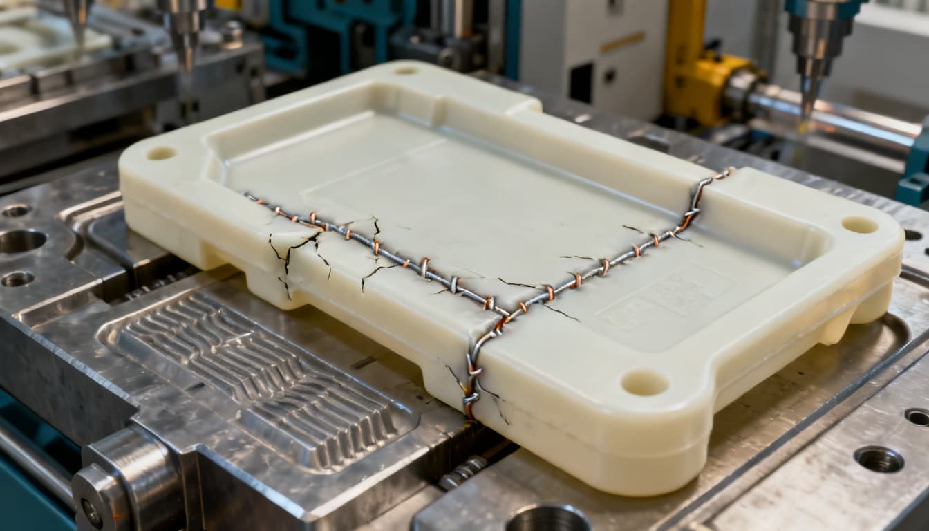
When Weld Lines Become Failure Points: A Troubleshooting Protocol for Load-Bearing Safe Plastic Components
In metal fabrication, few defects carry the same destructive potential as a cold lap—a condition where the filler metal rolls over the base metal without true fusion, creating a sharp notch that initiates cracks under cyclic loads. Similarly, porosity that resembles "Swiss cheese" inside a weld bead
Fusion Failures Aren't Just for Metals: Why Polymer Weld Lines Threaten Safety-Critical Plastic Parts
In metal fabrication, few defects carry the same destructive potential as a cold lap—a condition where the filler metal rolls over the base metal without true fusion, creating a sharp notch that initiates cracks under cyclic loads. Similarly, porosity that resembles "Swiss cheese" inside a weld bead and undercut grooves along the toe act as stress risers that can turn a load-bearing joint into a sudden failure. The industry’s response has been unequivocal: EV chassis, aerospace brackets, and medical equipment now operate under zero-tolerance mandates for critical weld flaws because a single lack-of-fusion defect can reduce structural margins below the safety factor.
Polymer processing is confronting the same physics, but the vocabulary is different. In injection molding, a weld line—also called a knit line—is effectively a lack of fusion between two melt fronts that meet inside the tool. When the component is a medical device housing, an automotive bracket, or a safety-critical power-tool handle, that microscopic parting plane becomes a silent structural liability. Weld lines in plastics don’t announce themselves with porosity or slag; they often look like a faint hairline, yet they can retain as little as 40% of the bulk material’s tensile strength. Engineers can no longer treat a weld line as a cosmetic afterthought—especially when the cost of field failure includes product recalls, regulatory action, and physical harm.
Key Takeaways: The same flaw mechanisms that grounded metal assemblies—cold lap, incomplete fusion, and stress concentration at the joint—are mirrored in injection molded parts. A troubleshooting protocol that treats every weld line as a potential failure point, rather than an unavoidable by-product, is the only way to meet the zero-tolerance expectation now common across safety-critical industries.
From Flow Fronts to Fracture Initiation: How Injection Molding Weld Lines Form and Why They’re Weaker
When two separate melt fronts converge—for example, around a core pin or after flowing through a multi-gate runner—the polymer chains at the interface do not fully entangle. Instead, the molecular orientation locks predominantly perpendicular to the flow direction, creating a plane of reduced chain interaction. Simultaneously, entrapped air, volatiles, or trace contaminants can get trapped at the meeting plane, further degrading consolidation. The result is a region that acts as a pre-existing crack front under tensile or impact loads. The strength penalty is not marginal; it’s often the dominant factor governing a part’s load-bearing capacity.
| Engineering Plastic | Typical Weld-Line Tensile Strength Retention | Notes / Failure Boundary |
|---|---|---|
| Polycarbonate (PC, unreinforced) | 60–70 % | Retention drops further with low mold temperatures; notch-sensitive. |
| ABS (general purpose) | 50–60 % | Rubber content helps, but flow-front degradation can reduce entanglement. |
| Nylon 6/6 (unreinforced) | 40–50 % | Moisture conditioning improves ductility but does not close the knit-line gap. |
| PBT (unreinforced) | 30–40 % | Fast crystallization quenches the knit line before full polymer diffusion. |
| Glass-filled PA 6/6 | 25–35 % | Fibers orient parallel to the weld plane, acting as internal stress raisers. |
Mold temperature is the single most powerful lever you have to improve these numbers. As JBRplas explains, a hotter mold keeps the interface above the glass transition temperature (Tg) long enough for additional polymer diffusion and chain entanglement. The practical limitation is cycle economics: every 10°C increase in mold temperature adds approximately 8–15% to the cooling time, depending on part wall thickness. That trade-off means a full thermal solution (elevating melt temperature as well) can raise production cost noticeably, but the alternative may be a part that fails an impact test at half the design load.
Before you adjust a single process parameter, follow the discipline that SILKBRIDGE recommends: define your acceptance criteria and obtain a baseline weld-line tensile bar molded under the current conditions. Weld-line strength depends on geometry, filling pattern, and processing history; without a quantitative reference, you cannot distinguish a real improvement from normal variation.
Process Tweaks, Part Redesign, or Material Upgrade: A Side-by-Side Look at Weld Line Mitigation Routes
When a weld line threatens a load-bearing safe plastic component, you typically have three intervention paths. Each has a different cost, lead-time, and risk profile. The table below distills the practical differences.
| Mitigation Path | What You Do | Benefits & Immediate Effect | Costs / Limitations |
|---|---|---|---|
| Elevate Melt/Mold Temperature | Increase melt barrel temperature 5–15°C and/or raise mold temperature, often with higher setpoints on the moving half. Follow JBRplas recommendation and monitor cycle time impact. | Fastest to implement. Delays skin solidification, enabling better chain entanglement. Can lift weld-line strength 10–20 percentage points in unfilled resins. | Extended cycle time (8–15% per 10°C increase), higher energy consumption, risk of material degradation, and possible sticking or flash. |
| Gate Relocation & Flow Leaders / Overflow Wells | Move the gate location to shift the weld line into a low-stress region; add flow leaders or overflow wells to steer the knit plane or absorb the contaminated front. Follow SILKBRIDGE’s one‑variable‑at‑a‑time protocol when testing. | Can eliminate the weld line from the critical cross-section entirely. Overflow wells also trap cold fronts, improving core strength. | Requires mold modification or new tooling. Adds material waste with overflow wells. Validation of the new gate location often demands additional Moldflow iterations. |
| Switch to a High Knit‑Line Strength Resin | Replace the current grade with a toughened PA, a PC/ABS blend, or a specialty grade designed to maintain entanglement at flow fronts. | May double or triple the weld-line strength without changing the tool. Some high‑flow PBT grades with impact modifiers can push retention above 60%. | Material re-certification, possible UL/ISO testing, higher raw material cost, and different shrinkage/warpage behavior. Not all families have a drop‑in substitute. |
Operationally, I treat these three paths not as alternatives but as a hierarchy to be applied sequentially. Start with thermal tuning because it costs almost nothing in tooling. If that cannot meet the requirement, gate relocation or flow modification becomes the next step. Resin replacement is the last resort for legacy tools where the weld line cannot be shifted out of the load path.
Cross-Industry Inspection Parallels: What Metal Welding Teaches Plastic Processors
The metalworking industry has developed a rigorous inspection toolkit for weld integrity; many of its principles transfer directly to injection molding. In metal, you visually search for porosity and undercut that look like Swiss cheese (Metalworkium), and you use dye penetrant or ultrasonic testing to expose cold laps along the weld toes (Xiris). For plastics, the analog is a hierarchy of tests: tensile bars taken right at the knit line, micro‑CT to visualize subsurface voids, and a quick Rockwell hardness spot check as a production‑floor proxy for fusion quality (PDHonline describes the adaptation of hardness testing for plastics). The table below maps the most useful metal-to-plastic inspection comparisons.
| Inspection Objective | Metal Welding Method | Plastic Injection Molding Method | Practical Considerations |
|---|---|---|---|
| Detect lack of fusion / cold lap | Visual inspection, dye penetrant, or ultrasonic (Xiris) | Destructive tensile or flexural test of the weld line; micro‑CT sections | Micro‑CT cost is high; reserve for root causes during process development. |
| Identify porosity or “Swiss cheese” voids | Radiography or macro‑etch (Metalworkium) | X‑ray computed tomography (CT) or sectioning/polishing | Porosity at the knit line often indicates trapped volatiles or wet resin. |
| Quick pass/fail softness check | Brinell or Rockwell hardness on weld metal (PDHonline) | Rockwell hardness reading along the knit line; soft spots signal poor fusion | Rockwell M or L scale on plastics; requires clean, flat surface. Good for production audits. |
| Verify material identity | Spectrometer or verification of ASTM A36 grade (Metalworkium) | Resin lot traceability, MFI check, and drying log review | Contaminated or off‑spec material is a common cause of weak weld lines. |
The crossover insight is clear: inspections designed to catch poor fusion in steel—cold laps, lack of penetration—have direct plastic counterparts. When you combine a quick Rockwell spot check at the weld line (as a production gate) with periodic tensile bar testing, you create a defense‑in‑depth inspection protocol that mirrors the metal industry’s best practices without breaking the budget.
The Engineer’s Field Protocol: Step-by-Step Troubleshooting to Rescue a Load-Bearing Plastic Part from Weld Line Failure
When a weld line is flagged as the root cause of a safety‑critical part failure, the following eight‑step protocol has repeatedly uncovered the true mechanism and pointed to a solution. It borrows verification habits from metal welding inspection (Metalworkium material verification), thermal‑energy modeling from JBRplas, one‑variable‑at‑a‑time testing from SILKBRIDGE, and hardness spot checks from PDHonline. Every failed weld line is a potential recall—the zero‑tolerance expectations set by automotive and medical OEMs apply to plastics just as they do to metals.
- Map the weld line location and the stress field. Use Moldflow or a comparable simulation to identify where flow fronts meet and overlay the FEA stress distribution. Mark every high‑tension zone that falls on a knit line.
- Verify the resin lot and drying process. Material contamination or moisture can slash weld‑line strength. Pull the lot certificate, check MFI, and confirm drying temperature, time, and dew‑point. This mirrors the material verification step advocated by Metalworkium for steel welding.
- Check and incrementally raise mold and melt temperatures. Measure actual steel and melt temperatures with a probe—not just controller setpoints—then increase mold temperature 5–10°C while logging the cycle time impact, as described by JBRplas. A small thermal bump often yields a measurable strength gain.
- Produce short‑shot progressions. Stop filling at 90%, 95%, and 99% to see exactly how the flow fronts meet. Look for asymmetric filling, hesitation, or gas trapping that may be pushing the weld line into a stress riser.
- Perform a destructive tensile or flexural test on parts containing the weld line. Cut coupons at the knit plane and compare them against the baseline non‑weld‑line material. The real‑world retention number will tell you how far you are from the acceptance threshold.
- If strength is still insufficient, modify the gate location or employ sequential valve gating. Move the weld line into a compression‑loaded boss or a sacrificial overflow tab, applying SILKBRIDGE’s one‑variable‑at‑a‑time protocol to validate that the relocation achieves the required strength.
- Apply a quick hardness spot check at the knit line. Use a Rockwell hardness tester with the appropriate scale for plastics (PDHonline reference). A soft reading across the weld line relative to bulk material is a reliable indicator of poor fusion in production.
- Document acceptance criteria and hold points for every safety‑critical batch. Define the minimum weld‑line tensile strength (e.g., ≥80% of bulk value), the inspection frequency, and the disposition rules if a part fails. This closes the loop and protects against field escapes.
This protocol transforms a fire‑fighting panic into a systematic engineering investigation. When you can trace every step to a quantified parameter—Moldflow result, Rockwell number, thermal data—the path from problem to solution becomes reproducible, and your buyer’s confidence in the process rises proportionally.
Injection Molders’ Tough Questions on Weld Line Integrity in Safety Components
Q: How much strength do we really lose at a weld line compared to the base material?
A: Loss varies by polymer: ABS typically retains 50–60% of bulk tensile strength, PC 60–70%, unreinforced nylon 40–50%, and PBT can drop below 40%. Glass‑filled grades often see a steeper relative drop because fibers align parallel to the weld plane. Always request a weld‑line tensile bar from the molder as a benchmark before accepting any process.
Q: Can we relocate the weld line to a low‑stress area without changing the mold gate location?
A: Mild melt‑temperature adjustments or filling‑speed profiles can shift the meeting plane slightly, but a significant relocation usually requires gate geometry changes or sequential valve gating. Overflow wells or flow leaders can help steer the knit line into a sacrificial boss or a non‑critical thickening. Validate any relocation with short‑shot studies.
Q: What’s a practical, quick quality check for weld line integrity on the production floor?
A: A simple drop‑weight impact test or a manual bending fixture on parts containing the weld line can expose brittle failure. For quantified data, use a tensile bar cut from the part at the weld line. Production‑worthy spot checks include Rockwell hardness readings along the knit line—soft spots indicate poor fusion, as described in PDHonline.
Q: Does post‑molding annealing actually heal weld lines in load‑bearing parts?
A: Annealing can relieve residual stress and slightly improve chain entanglement near the weld line, but it seldom restores strength to the bulk level. It is a supplemental step, not a substitute for proper process optimization. Always validate any assumed healing with destructive testing of a representative sample.
Q: What’s the acceptable strength threshold for a weld line in a safety‑critical component like a medical device housing or automotive bracket?
A: Many OEMs demand a minimum of 80% of the bulk material’s tensile strength at the weld line for primary load‑bearing features. The specific acceptance criteria should come from FEA safety factors and verification testing, and they must be defined before first‑article inspection, as SILKBRIDGE advises.
References & Further Reading
- Welding Defects Guide: Types, Causes and Prevention – Xiris
- How to Analyze and Prevent Welded Joint Failure Points – Metalworkium
- 16 Common Types of Welding Defects in 2026 – RapidDirect
- Welding Defects Guide 2026: Types, Causes, and Remedies – PranilGirase
- Injection Molding Weld Lines: Causes, Strength Risks, Solutions – SILKBRIDGE
- Weld Lines in Injection Molding — Formation, Strength Loss, Minimization – JBRplas
- Welding Inspection Qualifications & Hardness Testing (for plastics) – PDHonline
Nearly every injection molded part that carries a structural load will contain a weld line somewhere. The question is not whether the knit line exists, but whether it has been accounted for, measured, and hardened. If you’re engineering a safety‑critical component and need a manufacturing partner who treats weld lines as structural features, not cosmetic blemishes, get a quote and let’s run the protocol on your project.