3 Common Ultrasonic Weld Failures in Aerospace Injection Molding—and How to Prevent Them with Process Data
When a flight-critical bracket fractures during final assembly, the post-mortem rarely points to the ultrasonic welder alone. More often, the root cause sits two steps upstream—inside the injection mold cavity where melt fronts converged and never fully entangled. Weld lines, those hair-thin seams c
Why Hidden Molding Defects Turn Ultrasonic Welds into Liability Risks in Aerospace
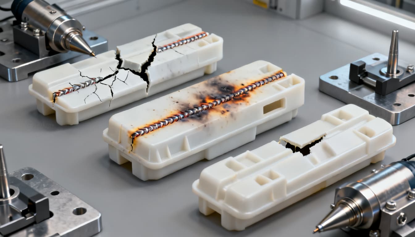
When a flight-critical bracket fractures during final assembly, the post-mortem rarely points to the ultrasonic welder alone. More often, the root cause sits two steps upstream—inside the injection mold cavity where melt fronts converged and never fully entangled. Weld lines, those hair-thin seams created when two flow fronts meet but fail to bond, act as pre-cracked initiation sites that ultrasonic energy cannot heal. According to Xometry Asia, these knit lines form where polymer chains meet at reduced temperature and pressure, leaving behind a visible seam and a structurally weakened zone [1]. In aerospace-grade thermoplastics like glass-filled PEEK or polyetherimide, the consequence is not cosmetic—it is load-path failure.
The problem compounds silently. InTouch Quality describes hair-like weld lines as "the result of weak material bonding, which lowers the strength of the part" [2]. When an ultrasonic horn delivers 20 kHz of mechanical vibration to a joint sitting directly atop such a weakened knit line, the energy that should create a homogeneous melt film instead propagates the existing micro-crack. What reaches the assembly technician looks like a clean weld, but peel testing reveals fracture along the original knit line—not through the welded interface. Elastron confirms that low melt temperatures during molding exacerbate this: "If two different flows meet together and are colder than normal, weld lines will appear" [3]. The molding process has already predetermined the ultrasonic outcome before the horn ever touches the part.
Even more insidious are internal voids and subsurface porosity—defects entirely invisible to visual inspection. RapidDirect notes that internal defects "occur within the metal material and are usually not open to the weld's surface" and are "detectable using methods like Ultrasonic Testing and Radiographic Testing" [4]. In plastic injection molded components, trapped gas pockets or shrinkage voids near the joint interface act as stress concentrators. When the ultrasonic horn compresses the energy director, these hidden cavities collapse unpredictably, creating uneven melt distribution and localized cold spots. For a bracket supporting avionics wiring under vibration loading, this failure mode remains dormant until fatigue cracks propagate to critical length—often discovered during scheduled maintenance rather than assembly inspection.
Key Takeaway: The ultrasonic welding process does not create these defects; it exposes them. Engineers who treat ultrasonic weld qualification as an assembly-step problem rather than a molding-process problem will repeatedly chase failures that originate in the injection mold.
How Energy Director Geometry and Molding Condition Interactions Determine Joint Integrity
The energy director is the geometric feature that makes ultrasonic plastic welding possible—a molded triangular bead, typically 0.4 to 0.6 mm in height, that concentrates ultrasonic friction into a single line of contact. When the horn descends, this sharp apex melts first, creating a controlled melt film that flows outward and entangles with the mating surface. But this elegant mechanism depends entirely on the director retaining its as-designed geometry through the injection molding cycle. Plastics Technology documents a failure pattern familiar to every experienced process engineer: "Injection mold wear can lead to a rounded energy director in the part, which produces a weak weld" [5]. A well-maintained mold produces a sharply pointed energy director that welds at lower amplitude with less flash; a worn mold rounds the peak, requiring higher energy input while delivering lower joint strength.
TWI's technical guidance on ultrasonic welding emphasizes that amplitude selection must match the joint design geometry and the polymer's melt characteristics [6]. For semi-crystalline polymers common in aerospace—PEEK, PPS, PEI—the sharp melting point demands precise amplitude control. Too little amplitude fails to initiate melt at the director tip; too much degrades the polymer before full collapse. This amplitude-geometry relationship means that a molded director deviating by as little as 0.1 mm from nominal shifts the entire process window.
The table below maps three recurring ultrasonic weld failure modes encountered in aerospace injection molding to their molding root causes, ultrasonic signatures, and the process data thresholds that should trigger intervention before parts reach assembly.
| Failure Mode | Molding Root Cause | Ultrasonic Signature | Process Data Threshold for Intervention |
|---|---|---|---|
| Weak knit-line fracture — joint separates along pre-existing weld line | Melt temperature < recommended processing range; two flow fronts cool below Tg before meeting | Erratic collapse distance; weld strength Cpk < 1.0 across 30-shot sample | Melt temp deviates >8°C from qualified setpoint; hold pressure drops >5% during cavity fill phase |
| Flash-over at joint face — molten material extrudes outside intended weld zone | Oversized or blunted energy director from mold wear; excessive melt cushion in barrel | Rapid collapse rate exceeding 0.5 mm/s; visible flash on >10% of part periphery | Energy director tip radius >0.15 mm (measured by CMM); melt cushion >3 mm for parts <50 g shot weight |
| Cold joint / incomplete fusion — director does not fully melt into mating surface | Insufficient hold pressure allows sink marks or voids near joint plane; moisture content >0.02% in hygroscopic resins | High weld cycle time variability (>15% CV); post-weld ultrasonic C-scan reveals unbonded regions >1 mm² | Hold pressure <80% of qualified value; resin moisture >0.015% at dryer outlet (measured by Karl Fischer titration) |
Each of these failure modes leaves a traceable fingerprint in the injection molding process data. The challenge in aerospace manufacturing is that parts often travel through multiple suppliers before reaching ultrasonic assembly—a molder in one facility, a welding station in another, and final integration at a third. Without a shared process data infrastructure, the ultrasonic technician sees only the failed weld, not the molding drift that caused it.
Tip: Establish a minimum incoming inspection protocol for molded parts destined for ultrasonic welding: measure energy director height and tip sharpness on 5 randomly selected parts per lot using a vision system or CMM, and reject any lot where the mean director height falls below 0.35 mm or the tip radius exceeds 0.2 mm.
Shear Joints vs. Energy Directors: Matching Ultrasonic Weld Design to Aerospace Part Demands
Not all ultrasonic joints are created equal, and in aerospace applications where vibration, thermal cycling, and structural loads converge, the choice between an energy director joint and a shear joint determines long-term reliability. An energy director concentrates melt initiation at a single line; a shear joint designs interference between vertical walls so that melting progresses along a controlled interface plane. Madison Group's design guidance warns that when a weld joint fails under structural load despite increasing the joint size per adjusted welding specifications, the problem often traces back to joint geometry selection made early in the design phase [7]. Choosing the wrong joint type for the loading condition leads to expensive steel re-welding into molds and re-machining—a timeline aerospace programs cannot absorb.
Ulite's technical reference specifies that a proper energy director is "a molded triangular bead at the joint that concentrates ultrasonic friction into one line, creating the melt film; typically 0.4–0.6 mm high" [8]. This dimension is not arbitrary—below 0.3 mm, the melt volume is insufficient for structural bonding; above 0.7 mm, collapse time extends and risks polymer degradation. Shear joints, by contrast, rely on an interference fit between sidewalls, typically 0.2 to 0.4 mm of interference per side, and are far more tolerant of mold wear because they do not depend on a sharp apex for energy concentration.
Material compatibility is non-negotiable regardless of joint type. Ulite's FAQ addresses a common inquiry directly: "Can you ultrasonic weld PP to ABS? No—dissimilar chemistries won't entangle. Use adhesives, mechanical fastening, or redesign to a compatible pair" [8]. For aerospace engineers specifying multi-material assemblies, this constraint drives material selection early in the development cycle.
| Comparison Metric | Energy Director Joint | Shear Joint | Selection Criteria & Failure Boundary |
|---|---|---|---|
| Joint strength (relative to base material) | 70–85% of parent material strength for amorphous polymers; 60–75% for semi-crystalline | 80–95% for both amorphous and semi-crystalline when interference is optimized | Shear joints preferred when joint strength must exceed 80% of parent material; required for pressurized enclosures per DO-160 |
| Tolerance to mold wear | Low — apex rounding >0.15 mm radius degrades melt initiation; mold maintenance intervals typically 100k–250k cycles | High — sidewall wear of 0.05 mm has negligible effect; mold maintenance intervals extend to 500k+ cycles | Energy directors demand tighter mold maintenance schedules; choose shear joints for high-volume programs with long tool life requirements |
| Typical aerospace material pairs | PEI–PEI, PC–PC, amorphous PEEK grades; best for unfilled or lightly filled (<20% GF) resins | PEEK–PEEK (all grades), PPS–PPS, PEI–PEI with glass fill up to 40%; handles filled materials without amplitude penalty | Glass-filled semi-crystalline materials create blunting risk for energy directors; shear joints eliminate this failure mode |
| Flash control | Moderate — flash tends to extrude outward from the joint line; requires flash trap groove for cosmetic/aerodynamic surfaces | Excellent — melt is contained within the interference zone; minimal external flash even at full collapse | Shear joints are the default choice for exterior surfaces or airflow-path components where particulate generation is prohibited |
| Dimensional tolerance sensitivity | High — 0.05 mm variation in director height shifts weld energy by 15–20% | Moderate — interference variation of ±0.05 mm shifts weld energy by 5–8% | Energy directors require tighter molding process control (±0.03 mm on director height); shear joints forgive normal molding variation |
The table reveals a clear pattern: shear joints offer superior robustness for aerospace-grade materials and operating conditions, but at the cost of more complex mold geometry and higher initial tooling investment. Energy directors remain viable for lower-stress applications where molding process control is already stringent—instrument panel bezels, interior trim clips, and non-structural enclosures. The decision point comes down to whether your supply chain can hold the molding tolerances that energy directors demand across the full production lifecycle.
From Mold Temperature Logs to Weld Quality Metrics: Process Data Workflow to Prevent Failures
Preventing ultrasonic weld failures before assembly requires a deliberate workflow that connects injection molding process data directly to weld quality outcomes. This is not theoretical—engineers at Tier-1 aerospace molders already pull melt temperature and hold pressure records to eliminate weak knit lines before parts ship [3] [2]. The workflow described below represents a practical implementation path that any injection molding buyer can specify in their quality requirements.
Step 1: Define Your Process Data Baseline
Begin with a 50-shot qualification run on the production mold and press. Record melt temperature (actual, not setpoint) at nozzle and hot-runner tip, hold pressure profile across all phases, and cavity pressure at the gate and at the farthest fill point. These curves, not just dimensional inspection reports, become your golden baseline. Any production lot whose process curves deviate beyond the control limits established during qualification should be quarantined for additional ultrasonic weld testing before release.
Step 2: Verify Energy Director Geometry with Quantitative Measurement
Pull 5 parts from each molding shift. Use CMM or laser profilometry to measure energy director height at three points around the joint perimeter. Record tip radius. If mean height drops below 0.35 mm or tip radius exceeds 0.2 mm, trigger a mold maintenance review. This simple check catches mold wear long before it produces parts that fail ultrasonic welding.
Step 3: Build Amplitude Profiles That Account for Material Lot Variation
Resin lots vary—even within the same grade from the same supplier. Pigment loading, filler distribution, and molecular weight shifts all affect ultrasonic energy absorption. Rather than running a fixed amplitude for every lot, execute a small Design of Experiments (DOE) on 10 molded parts from each new lot: vary amplitude ±10% around the nominal setpoint, measure weld strength via tensile pull, and select the amplitude that maximizes strength while minimizing flash. This 30-minute exercise prevents weeks of assembly-line troubleshooting.
Step 4: Implement Ultrasonic NDT Scan Plans with Documented Overlap
NASA PRC-6510 specifies ultrasonic inspection protocols that, while written for metallic welds, provide a rigorous framework applicable to plastic joints: "Scans shall provide overlap of 50% of beam width. The scan plan shall be included in the inspection report" [9]. For plastic aerospace components, this means programming your ultrasonic C-scan system to index at half the transducer diameter, ensuring no unbonded region larger than 1 mm² escapes detection.
Step 5: Maintain a Weld Strength Process Capability Database
The most powerful tool for preventing ultrasonic weld failures is historical data. Build a database tracking weld strength (peak load at break, in Newtons) for every production lot, indexed by molding process parameters, material lot number, and energy director measurements. After 12 months of production, you will have a reference distribution that flags anomalous lots before they reach assembly—and provides objective evidence for supplier corrective actions.
Checklist for incoming molded parts destined for ultrasonic welding:
- Request melt temperature and cavity pressure curves from the molding run—not just dimensional Cpk reports
- Measure energy director height and tip radius on a minimum of 5 parts per lot; reject if mean height < 0.35 mm or tip radius > 0.2 mm
- Verify resin drying records: moisture content must be < 0.02% for hygroscopic aerospace resins (PEI, PC, nylon)
- Perform ultrasonic C-scan on 3 randomly selected parts per lot with 50% beam overlap as prescribed by NASA PRC-6510 scan plan methodology
- Compare weld strength Cpk against your historical database; investigate any lot falling below Cpk 1.33 on peak load at break
Aerospace Weld Inspection Standards That Apply Even to Plastic Joints
A common misconception among injection molding buyers is that aerospace weld inspection standards apply only to metallic structures. In practice, the principles and acceptance criteria established by NASA for ultrasonic inspection translate directly to the non-destructive testing of injection molded plastic assemblies—particularly when those assemblies serve in flight-critical or safety-related functions. NASA PRC-6510, the Process Specification for Ultrasonic Inspection of Welds, mandates that "parent metal surface finishes shall be 125 μin RMS or better" for ultrasonic inspection [9]. For plastic molded parts, this surface finish requirement translates to specifying SPI/SPE finish grades of A-2 or better on joint surfaces to ensure consistent ultrasonic coupling and reliable flaw detection.
The standard's requirement for documented scan plans with 50% beam overlap is equally applicable to plastic assemblies. When qualifying an ultrasonic inspection procedure for injection molded aerospace brackets, the scan plan must define the ultrasonic beam path, scan index, and overlap percentage. This documentation becomes part of the First Article Inspection Report (FAIR) and is subject to review during customer or regulatory audits. MSFC-SPEC-3679 further reinforces these requirements by establishing general weld requirements that extend to all materials and joining processes [10].
| Standard / Specification | Key Requirement for Plastic Welds | Application in Injection Molded Part Qualification |
|---|---|---|
| NASA PRC-6510 | Surface finish ≤ 125 μin RMS on joint surfaces; 50% beam overlap on ultrasonic scans; documented scan plan in inspection report | Specify SPI A-2 mold polish on weld joint surfaces; require C-scan with indexed transducer and documented overlap; include scan plan in PPAP or FAIR package |
| MSFC-SPEC-3679 | General weld requirements for all materials including polymers; documentation of weld procedure specification (WPS) | Develop and maintain a WPS for each part number; record amplitude, collapse distance, hold time, and trigger force for every weld cycle |
| FAR 25.603 | Materials and processes must be approved and controlled; suitability and durability must be established by test or experience | Weld joint design and process parameters must be qualified through statistically valid testing (minimum 30 samples per lot for initial qualification) |
| DIZO Global Joint Design Guide | Optimized joint geometries for automotive, medical, and electronics—extrapolated to aerospace structural requirements | Reference for shear joint interference calculations and energy director dimensional tolerances across material families [11] |
For injection molding buyers, the actionable implication is clear: require your molding and welding suppliers to provide ultrasonic C-scan reports with documented scan plans for all flight-critical parts. The inspection report should include the transducer frequency, beam diameter, scan index, and overlap percentage—not simply a pass/fail determination. This level of documentation aligns with the aerospace industry's emphasis on traceability and provides objective evidence that hidden molding defects have not compromised the ultrasonic weld joint.
Note: While NASA PRC-6510 and MSFC-SPEC-3679 were originally developed for metallic structures, their acceptance by aerospace prime contractors as baseline inspection standards means that suppliers who apply these methodologies to plastic assemblies demonstrate a commitment to rigorous quality practices that exceeds typical commercial molding standards. Buyers should reference these standards in their procurement specifications even when the end application is not directly subject to NASA oversight.
Ultrasonic Weld Viability Q&A for Aerospace Injection Molded Parts
Q: Can you reliably ultrasonic weld glass-filled PEEK to itself for aerospace brackets?
Yes, with tight process control. Glass-filled PEEK presents two specific challenges: the glass fibers can blunt the energy director tip during molding (the abrasive filler erodes the sharp apex as the polymer shrinks around it), and the semi-crystalline nature of PEEK demands precise amplitude control to initiate melt at the sharp melting point without degrading the polymer. The solution is a three-part protocol: first, verify energy director sharpness post-molding using CMM or vision inspection—reject any lot showing tip radius exceeding 0.15 mm. Second, use 15–20% higher amplitude than unfilled PEEK (typically 60–80 μm peak-to-peak for 30% GF PEEK vs. 45–60 μm for unfilled). Third, employ a slower collapse rate (0.2–0.3 mm/s) to allow the larger melt volume generated from the filled material to flow and entangle fully. Parts qualified under this protocol have demonstrated joint efficiencies exceeding 85% of parent material strength in aerospace bracket applications.
Q: How do colorant or additive batches affect the ultrasonic weld process window?
Pigments and fillers alter melt viscosity and ultrasonic energy absorption characteristics in ways that are often overlooked during material qualification. Carbon black, titanium dioxide, and organic pigments each shift the material's damping coefficient—the measure of how efficiently the polymer converts ultrasonic mechanical energy into heat. Even a 1% colorant variation can shift the optimal weld amplitude by 5–8%, pushing a previously stable process out of its window. The correct protocol is to treat each new colorant lot as a material change: run a small DOE (3 amplitudes × 3 collapse distances, 5 samples per condition) on actual molded parts from the new lot, measure weld strength via tensile pull, and establish the new amplitude setpoint. Document the colorant lot number alongside the weld parameters in your process database. This practice prevents the frustrating scenario where parts that welded perfectly last week suddenly exhibit cold joints or flash-over with no apparent change in the welding machine settings.
Q: What is the minimum energy director height before mold wear requires tool maintenance?
As a rule grounded in both joint design theory and field experience, the energy director should maintain 0.4–0.6 mm height with a sharp apex (tip radius ≤ 0.1 mm). When CMM measurements show rounding such that the tip radius exceeds 0.15 mm, or the absolute height drops below 0.3 mm, weld strength drops sharply—typically 30–40% below the qualified baseline. At this point, mold refurbishment is required. The mechanism is straightforward: a blunted or shortened director cannot concentrate sufficient ultrasonic energy density to initiate melt quickly. The welding machine compensates by increasing cycle time and energy input, but the resulting joint suffers from excessive flash, polymer degradation at the interface, and incomplete molecular entanglement. Establish a mold maintenance trigger at 0.35 mm director height to provide a buffer before reaching the critical 0.3 mm threshold. For high-volume aerospace programs (100,000+ parts annually), budget for mold refurbishment every 150,000–250,000 cycles on energy director features.
Q: How do we qualify a new injection molder using process data instead of just part dimensions?
Traditional molder qualification relies on dimensional inspection of molded parts—first article reports showing that length, width, and hole positions fall within tolerance. This approach is insufficient for parts destined for ultrasonic welding because it ignores the internal material state that determines weldability. A proper process-data qualification requires: (1) melt temperature and cavity pressure curves from a 50-shot production run, overlaid against your qualified golden baseline—the new molder's curves must fall within ±2σ of the baseline at all phases; (2) energy director geometry measurement on 10 random parts per cavity, with Cpk analysis for height and tip radius; (3) ultrasonic NDT with documented scan plans (per NASA PRC-6510 methodology) on 10 welded assemblies produced from the molder's parts; (4) comparison of the new molder's weld strength Cpk against your historical database—a Cpk below 1.33 or a mean shift exceeding 10% triggers rejection. This data-centric approach catches molding process deficiencies that dimensional inspection alone would miss, such as incorrect melt temperature leading to weak knit lines that surface only during ultrasonic welding.
Q: Does ultrasonic welding meet FAR 25.853 flammability requirements for cabin interiors?
Ultrasonic welding itself does not change the base material's flammability rating. If the injection molded resin (polycarbonate, PEI, PPS, or other aerospace-grade thermoplastic) has an approved FAR 25.853 test report demonstrating compliance with the 12-second vertical burn test and smoke density requirements, the ultrasonically welded assembly will maintain that rating—provided no flammable adhesives, coatings, or dissimilar materials are introduced at the joint. The key caveat: verify that the welding process does not introduce degradation byproducts at the joint interface. Excessive amplitude or prolonged weld time can thermally degrade the polymer, creating low-molecular-weight species that may exhibit different flammability characteristics than the parent material. For cabin interior components, include a FAR 25.853 burn test on welded assemblies (not just on base resin plaques) as part of your qualification protocol, and document the weld parameters used so that production parts are manufactured within the tested process window.
References & Further Reading
- 16 Common Injection Molding Defects: Types, Causes, and Solutions — Xometry Asia
- Injection Molding Defects: 11 Types & How to Prevent Them — InTouch Quality
- 11 Injection Molding Defects and Troubleshooting — Elastron
- 16 Common Types of Welding Defects in 2026, Causes and Remedies — RapidDirect
- What Happened to Your Ultrasonic Weld Quality? — Plastics Technology
- Ultrasonic Welding — Component Design and Weld Parameters — TWI
- Design Like You Mean It: Ultrasonic Welding — Madison Group
- Beyond the Press: Ultrasonic Welding and Assembly for Injection Molded Plastic Parts — Ulite
- Process Specification for Ultrasonic Inspection of Welds — NASA PRC-6510
- Weld Requirements — MSFC-SPEC-3679
- Ultrasonic Welding Joint Design Guide — DIZO Global
The recurring ultrasonic weld failures that plague aerospace injection molding programs—weak knit-line fractures, flash-over at the joint face, and cold joints from incomplete fusion—share a common origin: they are molded into the part before the ultrasonic horn ever touches it. Process data from the injection molding cycle provides the earliest and most reliable warning that a weld failure is imminent. By establishing a workflow that connects melt temperature curves, energy director geometry measurements, material lot-specific amplitude profiles, and documented ultrasonic NDT scan plans to historical weld strength databases, engineering teams can intervene before defective parts reach assembly. For injection molding buyers, specifying these data requirements in procurement documentation transforms ultrasonic welding from a source of recurring liability into a controlled, predictable joining process.
For support qualifying your aerospace injection molding supply chain with process data-driven ultrasonic weld validation, get a quote from our engineering team.